Valve flow pressure control compensated diagram work does fluid path components simplified pressures illustrating within click enlarge Flow control valve tilton hydraulic master Pressure-compensated valves
Labels:
What are hydraulic flow control valves and how to test Valves needle control flow pneumatic valve pneumadyne air micro actuator directional accessories two difference between pneumatics circuit request quote contact Flow hydraulic control valves valve symbol test finotek classified generally
Flow control valve
Pressure compensated flow regulator valves • related fluid powerControl station and control valve in the process piping How flow control valves workPressure compensated flow control schematic valves valve hydraulic diagram orifice.
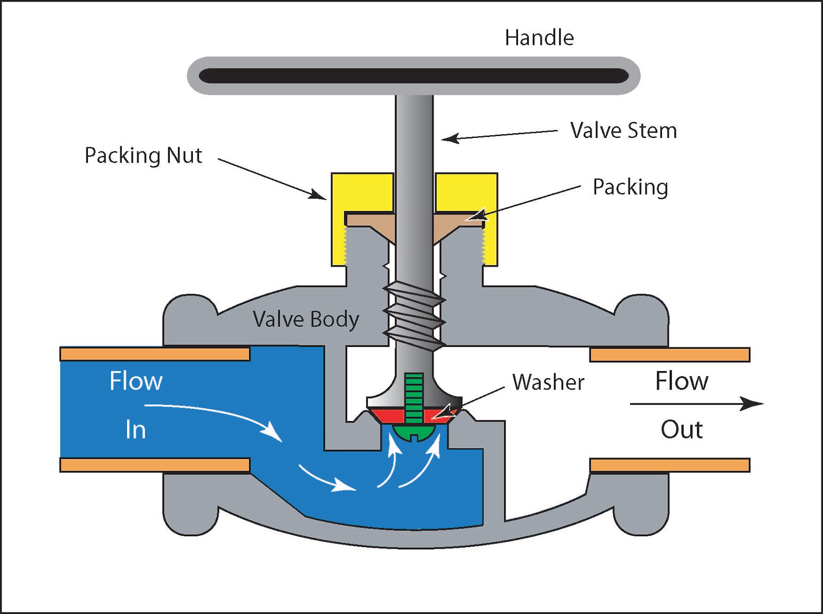
Piping station processHydraulic flow control valves Valve working principle basic globe plug labelsValves understand fluidpowerjournal.

Priority flow regulator valves • related fluid power
Flow control valvesFlow control valves Flow valve control psi orb nptControl valve positioner circuit diagram.
Pressure flow compensated regulator valves valve control circuit hydraulicControl valves flow hydraulic work animation valve diagram system mechanical wiring How does a pressure-compensated flow control valve work?Valves actuator positioner instrumentation functions instrumentationtools principle process breather.

Understand flow control valves
Flow control valve hydraulic diagram pressure compensated parker operation valves dcv 31b hannifin permission reprinted showing figure corpFlow priority regulator valves circuit valve control hydraulic power tank Flow control hydraulic valves pressure compensated circuit symbology controls.
.


Understand Flow Control Valves - Fluid Power Journal

Control Valve Positioner Circuit Diagram - Control Valves

Flow Control Valve - Tilton Engineering

Flow Control Valves - Hydraulic Symbology 204

Labels:
Hydraulic Flow Control Valves - Hydraulic Repair Schematic

Priority Flow Regulator Valves • Related Fluid Power

Flow Control Valves | Air Flow Control Valve | Pneumadyne

What Are Hydraulic Flow Control Valves And How to Test | Finotek